Our quality assurance system is certified in accordance with the ISO 9001 standards. An independent quality assurance department is responsible for all working procedures required to ensure that all manufacturing processes are carried out in accordance with international technical delivery conditions like ASTM/ASME, EN, API and with the customer specifications.
Our Factory could provide the followings Methods of cutting steel to meet for customer request, According to customer request to choose different equipment;
1. High pressure water jet waterjet water cutting
2. Step punching
3. Scythe scissors
4. Disc shears
5. Saw
6. Grinding wheel cutting
7. Laser cutting
8. Plasma arc cutting
9. Manual cutting
Our quality assurance system is certified in accordance with the ISO 9001 standards. An independent quality assurance department is responsible for all working procedures required to ensure that all manufacturing processes are carried out in accordance with international technical delivery conditions like ASTM/ASME, EN, API and with the customer specifications.
Furthermore RuiXiang has been certified in accordance with the OHSAS 18001 to secure the occupational health and safety of our employees and to eliminate and minimize the risks associated with their activities.
RuiXiang has several third party approvals for their manufacturing process as well as customer approvals.
Third party approvals
American Bureau of Shipping
Selection of customer approvals
Saudi Aramco
Bureau Veritas
Shell International
Det Norske Veritas
Kuwait Oil Company
Germanischer Lloyd
Petroleum Development Oman
Lloyd”s Register
Sabic
PED
Gasco
Destructive & non-destructive testing (In assuring the quality of our products, our own in-house testing facilities play an important role. Our laboratory is well equipped to perform a wide variety of both destructive and non-destructive quality tests.)
Destructive testing includes
tensile tests
Non-destructive testing includes
eddy current testing
impact tests
x-ray testing
bend tests
hydro testing
hardness tests
ultrasonic testing
intercrystalline corrosion test
positive material indentification testing
pitting corrosion test
–
metallurgical tests
–
Which type of tube cutting machinery to use for an operation depends on the tube requirements:
What production rates are required?
What end condition is required of the cut part?
How is the stock material supplied— random lengths or coil stock?
Is the tubing produced in-house or supplied from an outside producer?
Will the tubular part be fabricated entirely in-house, or will it be sent to another fabricator for finishing?
Sawing
Sawing is one of the most versatile and widely adapted methods for cutting tubing. Each sawing application is unique, but, generally, sawing is suitable for low-volume production.
The most important consideration in sawing is applying the correct blade to the tube to be cut. In all sawing applications, the number of teeth required on the blade is based on the number of teeth that contact the tube on the maximum arc of the cut. Having too few teeth contacting the tube limits production rates and causes vibration. Having too many teeth contacting the tube causes chips to become clogged in the teeth, perhaps causing the teeth or the blade to break.
Two types of sawing machines are used—the cold saw and the band saw.
In principle, cold sawing is the same as turning and milling. Metal is removed by shearing with positive rakes. The basic blade design for cold sawing is a common tooth shape, but others also are used. On thick-walled tubing, specialized bevels are used to break the chip. The cutting zone is cooled to minimize saw tooth softening by lubricating it with soluble oil emulsions or synthetic oil directly in the cutting zone. Flood systems can be used to deliver large quantities of coolant, needed for heavy-wall applications.
The cold sawing process has been adapted to a variety of machines, with varying levels of production capability. A single-head cold saw cuts one tube at a time, although it can cut a bundle of small diameter tubing at once (see Figure 1). Multihead sawing machines can have up to 12 saw heads and cut tubing into multiple pieces.
Cold sawing advantages:
Single-head cold sawing is relatively inexpensive.
Multihead saws are capable of high production rates.
Cuts square and rectangular shapes, as well as rounds.
Cuts both heavy- and light-wall material.
Cuts materials from mild to stainless steels.
Special single-head saws make angle and miter cuts.
Cut-end condition is good when blades are sharp—minimal burr and distortion result.
Cuts a bundle of small-diameter tubing at once. Some cold saws can cut two 1.25-in.-OD tubes at a time.
Because the entire kerf loss is milled into chips, scratches and other problems can result during packaging or secondary operations.Cold sawing disadvantages:
A tube cleaning operation may be needed.
On multihead saws, length tolerance can be difficult to maintain.
On multihead saws, changeover time for part lengths and saw blades can be long, depending on the number of saw heads used.
The need to resharpen blades frequently when cutting certain materials may reduce production rates.
When the blades become dull, a large hanging burr occurs on the cut end.
Can distort very thin-wall tubing.
Band sawing is suitable for cutting entire bundles of tubing into shorter lengths. It can cut a large bundle, up to 40 by 40 in., of large, heavy-walled square and rectangular tubes into sections. No other method is able to do this as efficiently. However, the tubes have a tendency to drift during bundle-cutting, causing an out-of-square cut. Round tubes may spin during the cutting cycle, so it may be necessary to tack-weld one end of the bundle to prevent the tubes from shifting and spinning. This can be time-consuming and wasteful.
Band sawing has limited usefulness in cutting a single tube, although some special single-head band saws can miter-cut single tubes. It is most suitable for cutting diameters greater than 5 in. OD and heavy-walled sections.
Band sawing advantages:
Cuts an entire bundle of tubes.
Makes angle and miter cuts on special single-head saws.
Band sawing disadvantages:
Tack welding one end of the bundle may be needed to prevent the tubes from shifting and spinning.
Lathe Cutting
Two types of lathe cutting have been adapted for tube cutting. The standard lathe has been used for many decades. A tube is fed through a chuck-type clamping mechanism, the tube is rotated, and cutting tools (inserts) mounted on slide mechanisms part the tubing.
Because the tube rotates, its length cannot exceed 20 ft. This length limitation can slow production rates.
Another lathe type (rotary lathe) spins a rotary cutting head around a stationary tube (see Figure 3). Up to four cutting tools can be mounted on the rotary head. This type of machine can cut the part and perform internal and external chamfering on it. Optional adapters allow internal and external chamfering on the back side of each part.
Lathe cutting’s only application is on round tubes. Typically, it is used to cut high-strength, heavy-walled tubes for components such as bearing liners (52100 steel) and air bag canisters and exotic materials such as titanium and INCOLOY® alloys for components such as automotive axles.
Lathe cutting advantages:
Cuts all material types—mild and stainless steels; aluminum; copper; bronze; and high-strength, low-alloy (HSLA) steels.
Cuts a range of diameters—0.375 to 8.00 in.—and wall thicknesses—0.020 to 0.500 in.
Can produce finished, precision parts in one operation.
CNC is available.
Carbide inserted tooling facilitates fast changeovers.
Cutting process uses dry or fine mist coolant, so no filtration system is needed for coolants.
Lathe cutting disadvantages:
Fully automated systems are relatively expensive.
Cycle times are comparatively slow.
Profiles that can be cut are limited to round tube.
Tube length needs to be short when using the standard lathe cutting method.
The part needs to be chamfered to avoid ID distortion.
The cutting tooling inserts produce a significant amount of chips.
Rotary Cutting
Rotary tube cutting has been used in the industry for more than 50 years. Initially it was used in the aluminum tubing industry to cut air-conditioning tubing. As the technology has advanced, its use has expanded to all types of materials and products.
Rotary tube cutting involves parting off round tubing using a cutting blade that rotates around the tube diameter (see Figure 4). The tube is held in position on backup rollers while the rotary cutting blade (wheel) rotates as it cuts into the tube.
Because no kerf or chips are produced by this method, there is no material loss. Instead, the tube material is displaced—pushed toward the face of each side of the cutting blade. This is why a slight angle is produced at the cut end of the tube. Some material is pushed to the tube’s ID and a slight amount to the OD, creating a slight bulge on the tube’s cut end.
This method is suitable for cutting straight sections of 20- to 25-ft. tubing, or for cutting a coil of tubing, which can be uncoiled and straightened during the cutting process.
The main applications for the rotary method are fabricating aluminum automotive air-conditioning lines, steel automotive fluid transfer lines, copper HVAC components, and, to some extent, general carbon steel components.
The traditional rotary cutting machine tends to distort the tube ID. Technology improvements have been developed to try to improve the cut quality and reduce ID distortion.
Rotary cutting advantages:
No material loss between cuts.
No significant burr.
No kerf or chips are produced.
Can be integrated with secondary operations such as grooving and chamfering.
Can achieve high production rates on short part lengths.
Cuts soft materials such as aluminum and copper.
Cuts coiled material or straight lengths.
Rotary cutting disadvantages:
Can produce metal fatigue at cut ends, which can be detrimental to secondary operations.
Profiles that can be cut are limited to round tube.
Tube ends do not cut square. A slight OD chamfer is produced, and an inside burr and distortion also can result
Tool life is shortened when cutting hard materials.
Supported Shear Cutting
The shearing sequence begins when a mill length of tubing stock is loaded onto the machine through the external dies of both tooling sections and over both internal punches. A pusher advances the tubing to an adjustable stop finger located behind the movable tooling. The stop finger is adjusted to the cut length. When the tubing hits a stop mechanism or a preprogrammed length, the shearing cycle begins. The material is sheared between the stationary tooling section and the movable tooling section, similar to the cutting action of scissors.The supported shear cutting method was developed in the U.S. more than 50 years ago. A supported shear cutting machine is equipped with two sections of tooling—one stationary and one movable. Each tooling section contains an internal punch and an external die. The stationary tooling section supports the tubing’s hollow interior with an internal punch and supports the exterior with a close-fitting external die (see Figure 5).
On some equipment, the movable section moves vertically first and then moves horizontally. On others, the movable section performs an elliptical loop to complete the cut.
At the end of the cutting cycle, the movable section returns to a fixed position, concentric with the stationary section, and the next tube to be cut is advanced. This ejects the cut segment and the process is repeated.
Supported shear cutting advantages:
No material loss between cuts.
High-quality cut, with no burr.
Cuts all types of materials.
High cycle rates on parts shorter than 24 in.
Long tool life before resharpening is required.
Cuts square and rectangular shapes, as well as rounds.
Cuts light- and heavy-wall tubing.
Supported shear cutting disadvantages:
Mill-length tubes must be very straight.
Mill-length tubes should have minimal ID weld flash.
Cut quality depends on precise fit of ID and OD.
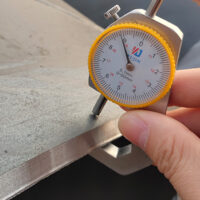
Dual Blade Shear Cutting
Blade shearing of tubing has been used for more than 75 years. Dual-blade shear cutting succeeds single-blade shear technology. Dual-blade was developed to eliminate the dimple that typically results on the tube end during single-blade shear cutting.
With this method, the tubing is held in clamping dies. A horizontal blade makes an initial scarfing cut through a portion of the tube wall so that the vertical blade encounters less resistance and pierces the tube wall without dimpling (see introductory photo).
It is most suitable for carbon steels and alloy steels, including ferritic stainless steels.
Each tube diameter requires its own set of clamping dies. The clamping dies are hardened and ground to precise tolerances. They are relatively inexpensive and can be resharpened for use for up to 3 million cuts. Four clamping die sections are assembled into two sections, allowing them to open and close to feed and clamp the tubing and to provide clearance for the horizontal and vertical blades.
During the cutting process, the horizontal blade removes only a small amount of material, but this is necessary to create the notched area for the vertical blade to enter. The initial penetration of the vertical blade directs the slug to the inside of the tube. This slug folds in under the blade and is pushed through the bottom of the tube.
Depending on wall thickness and diameter, the end cut may have some burr and sharp edges.
Dual-blade shear cutting advantages:
Cuts square and rectangular shapes, as well as round.
Cuts tubing from straight lengths or from coiled stock.
Can be integrated with secondary operations.
The cut is square and distortion-free.
Overall length tolerances of 0.010 in. are attainable.
Has quick-change tooling.
Can be integrated with bundle loaders for high-volume cutting.
Production rates up to 7,000 cuts per hour are possible.
Dual-blade shear cutting disadvantages:
Range of materials it can cut is limited to 0.125 to 6.50 in. dia. and wall thicknesses from 0.020 to 0.250 in.
On certain sizes, burr and sharp edges are present.
Laser Cutting
The first working lasers were developed in 1960. By 1969 industrial lasers had been applied to a variety of welding and cutting operations. Laser cutting technology uses a power source that generates a beam of electromagnetic (EM) radiation. The beam has a specific wavelength, and these wavelengths are uniform, parallel, and in phase with each other (see Figure 6).
The two most widely used laser systems are the carbon dioxide (CO2) and the neodymium suspended in a yttrium aluminum garnet crystal (Nd:YAG).
Lasers are used most often to cut complex tubing parts that require multiple successive procedures such as drilling, punching, milling, sawing, and deburring. Laser cutting enables the complete processing of a part in one operation, on a single machine, using a single tool. Successive secondary operations can be eliminated. Laser cutting is not an efficient method to produce one type of profile, such as only square tubes.
In addition, laser cutting is well-suited for on-demand and small-batch production and when many modifications are needed.
Laser cutting advantages:
Can be used for practically almost all tube shapes.
Suitable for complex parts.
Suitable for small-batch production.
Some secondary operations may be eliminated.
Cut quality is good.
Laser cutting disadvantages:
Most systems are relatively expensive, compared to other cutting methods. • Serious consideration should be given to the entire production process, including maintenance and operating costs, as well as potential savings from reduced labor, handling, and secondary operations costs to ensure an acceptable return on investment (ROI).
Not an efficient method for producing one profile or a simple operation.
Marking Workflow
1.Ensure all tests are performed on piping system before starting painting work.
2.Clean painting surface to remove oils, grease, dirt.
3.Ensure proper room temperature and humidity levels.
4.Use hand tools, machine tools, shot blasters etc to clean surface as per relevant standards and project requirements.
5.Apply primer within 4 hours of surface preparation.
6.Apply paint coats after previous coats have dried up, as per instructions of paint manufacturer. Note:Stainless steel piping is not painted. Identification marking may be done on this piping. Marking on steel pipe
1.Manufacturer name or his registered trademark;
2.Standard of steel products;
3.The grade of the material;
4.The heat number;
5.Pipe number;
6.Wall thickness;
7.Actual length;
8.Out diameter;
Bending Processes
There are common types of bending processes. Those types are compression bending, ram bending, roll bending, and rotary draw bending. Ram bending is more of the traditional type bending seen in automotive shops still today. It uses a hydraulic ram that pushes the steel tube against the rollers. The roll bending procedure is usually used for construction type bending. This method uses three rolls and generally are for larger pieces.
We can manufacture extension pipe-bends according to your individual specifications (dimensions, drawings, samples). Also we can manufacture special pipe bends according to your sketches. In addition to our standard steel stock programme, we also process aluminium.For use in clean air pipe systems, pipe bends with small bending radius are the ideal alternative to pipe bends type/norm 3 with welded leg extension.
Piping Spool, Piping System
Pipe spool is a prefabricated component of a piping system.
Type of product
Size
Steel
Construction
Piping Spools
As per drawing
Carbon Steel & Stainless Steel
Seamless & Welded
Why use the pipe spool?
1. Pipe spools is a proven means for reducing field installation costs while providing the highest of quality in the products fabricated.
2. Pipe spools are often flanged to facilitate the connection to other spools. The fabrication of these spools is normally performed by specialist fabrication companies which are equipped with the required infrastructure.
Packaging methods for steel pipe would vary depending on the type and size of the pipes.In this article ,SHEW-E STEEL will provide the packaging methods applied for the most common types of piping,but additional packaging precautions should be taken in some cases to prevent damages mainly caused by the wiggling and bending during the sealift handing and transportation stages and process.
Bundled package
On bundle of steel tube shall be the same in batch number, steel grade and specification.the rest of tubing less than one bundle should be tied into small bundles.
The weight of each bundle should be less than 50kg.The max weight cannot exceed 80kg of the bundle If there are special requirements.
When the length of the steel tube is greater than or equal to 6m, with at least 8 strapping bands for each bundle, divided into 3 groups and 3-2-3.
When the length of the steel tube is less than 6m, and each bundle is tied at least 5 knots and divided into 3 groups, which are 2-1-2.
When the length of the tube is greater than or equal to 3m, and each bundle is tied with at least 3 bands, divided into 3 groups, 1-1-1 showed below.
Wooden box package
The wooden box is suitable for cold rolling or cold drawing seamless steel tube, polished hot rolled steel tube.
When the outer diameter of steel pipe is greater than or equal 10mm, the maximum weight of the container should be 50kg.
When the outer diameter of steel pipe is less than or equal 10mm, the maximum weight of the container should be 30kg.